Hardware
The “machine control unit” (MCU) devices use ESP32 microcontrollers; our reference builds use ESP32-DevKitC / ESP32-WROOM-32D boards such as these from Amazon. For reasons described in the introduction we use ESPHome as the software on the ESP32s.
Version 1 Hardware
This describes the initial Version 1 MCU hardware, essentially a prototype assembled from off-the-shelf components and fitted in a 3D printed enclosure.
Components
The following table lists the components required for the Version 1 MCU hardware. Costs are approximate as of November 2025 and may vary, and do not include fasteners, hookup wire, and incidental parts.
Item / Description |
Qty |
Link |
Cost (USD November 2025) |
|---|---|---|---|
3D Printed Enclosure and Laser Cut Card Holder |
1 |
$9.90 |
|
ESP32 38-pin wide dev board [1] |
1 |
$5.66 |
|
Screw terminal breakout board for ESP32 |
1 |
$8.13 |
|
16x2 backlit character LCD display with I2C backpack (PCF8574T) |
1 |
$3.99 |
|
4-channel bi-directional 3.3v/5v level converter |
1 |
$0.75 |
|
Clockless 12mm WS2812-type addressable RGB LED [2] |
1 |
$0.32 |
|
3.3v controlled optoisolated relay module (up to 10A) [3] |
1 |
$1.29 |
|
16mm red LED-backlit momentary pushbutton with shield/cover [4] |
1 |
$5.49 |
|
Wiegand protocol 3.3-5VDC RFID reader with card present output [5] |
1 |
$6.26 |
|
M12 8-pin A-code male connector, prewired, for control box [6] |
1 |
$9.80 |
|
M12 8-pin A-code female connector to blunt end wire, 1-3m length as needed [6] |
1 |
~$15.49 (2m) |
|
Control Box Sub-Total |
$67.08 |
||
optional 5VDC 2.5A Power Supply, if needed [7] |
$12.90 |
||
optional 30A relay for high current machine control [8] |
$9.79 |
||
optional 25A solid state relay for high current machine control [8] |
$7.49 |
||
optional 40A 240V contactor 2-pole contactor for 240V machine control [8] |
$11.99 |
||
optional Junction box for housing high current relays/contactors - Carlon E987R 6x6x4” [9] |
$19.26 |
||
optional Cord lock for plug-in junction box [9] |
Amazon (large) |
$14.98 |
Component Notes:
Wiring
This is intended to work with https://github.com/jantman/machine-access-control/blob/main/esphome-configs/2024.6.4/no-current-input.yaml. Note that a standalone (non-networked) ESPHome configuration for verifying the operation of all hardware, along with instructions for using it, can be found in https://github.com/jantman/machine-access-control/tree/main/esphome-configs/2025.11.2.
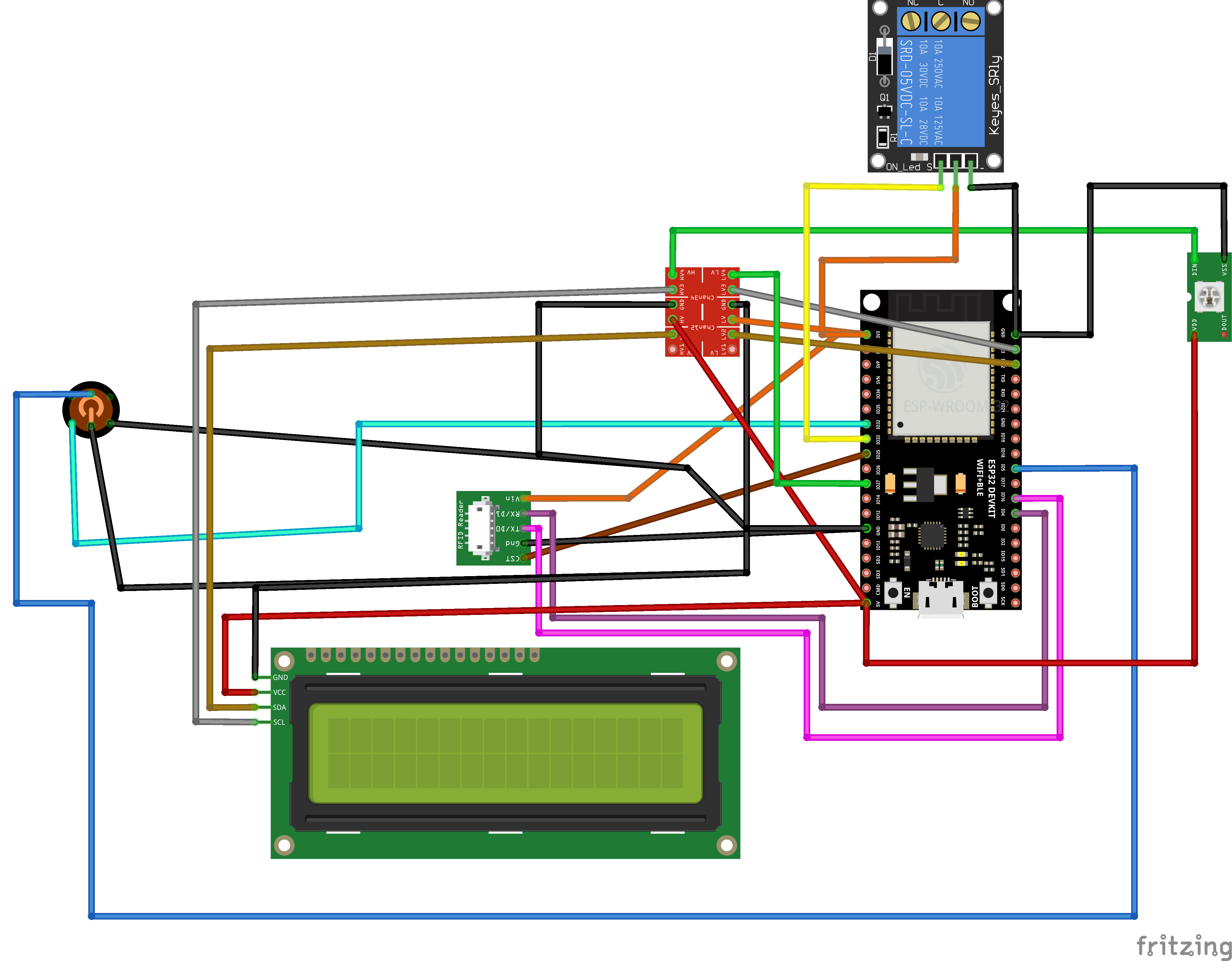
RFID Reader - Note that if using the same model that I did, you must add a solder blob on
S2for Wiegand output.CSTtoGPIO18Gndto groundTX/D0toGPIO16RX/D1toGPIO43.3-5Vto 3v3
Level Converter
Gnd and Gnd to ground
LV to ESP32
3v3HV to ESP32
5v2 -
LV2toGPIO22;HV2to LCDSDA3 -
LV3toGPIO23;HV3to LCDSCL4 -
LV4toGPIO27;HV4to NeopixelD1
Pushbutton
LED
-toGndLED
+toGPIO5Switch
NCtoGndSwitch
ComtoGPIO32
Neopixel
5vto5v(often red)GndtoGnd(often blue)D1to Level ConverterHV4toGPIO27(often white)
LCD Display
GndtoGndVCCto5vSDAto Level ConverterHV2toGPIO22SCLto Level ConverterHV3toGPIO23
Optoisolated Relay - Output is N.O.
GndtoGndIntoGPIO33VCCto3v3
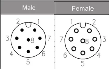
M12 8-pin A-code connector for power, control, and additional inputs. The MCU should have the female socket which has visible pins in it, and the wire going to it should have the male plug which has a housing that accepts those pins. Note that M12 A-code connectors have an alignment notch, a ring of 7 contacts, and one central contact. On the male connector (the one with pins), contacts are numbered 1-7 clockwise from the alignment notch with 8 in the center. There is also an industry-standard color code for the wires, shown below.
1(white) to +5VDC power in2(brown) to power supply ground3(green) to relay input / common4(yellow) to relay output Normally Open5(grey) to ESP32GPIO12for tamper switch (not yet implemented in software)6(purple) to ESP32GPIO14for future use7(blue) reserved for future ammeter / current clamp use (not implemented in V1)8(red) reserved for future ammeter / current clamp use (not implemented in V1)
Enclosure
There is an example enclosure for the unit, 3D printed with a few laser cut parts, in the hardware/v1_mcu directory of the GitHub repo. See that directory for information on fabrication and assembly.
ESPHome Configurations
Example ESPHome configurations for various ESPHome versions and various hardware combinations can be found in the esphome-configs/ directory of the git repo broken down by ESPHome version. New installations should always use the newest supported ESPHome version, as bug fixes and features are not backported to earlier versions of these configs.
All of the example ESPHome configurations begin with a substitutions key, which contains a machine_name substitution. This must be set to the same name as used in the machines.json config file. If desired, you can override the esphome name and friendly_name values (though this is not recommended).
The ESPHome configurations are based on a ESPHome secrets.yaml file for substituting in sensitive values and installation-specific values using the !secrets substitution operator. The example configurations expect the following secrets to be defined:
- api_encryption_key
this is needed for the ESPHome web UI functionality, like wirelessly streaming logs. See ESPHome docs.
- ota_password
A password used for OTA updates from ESPHome. See ESPHome docs.
- wifi_ssid
WiFi network SSID to connect to. See ESPHome docs.
- wifi_password
WiFi network password. See ESPHome docs.
- domain_name
Domain name to use for DNS. See ESPHome docs.
- mac_url
the full URL to the /api/machine/update endpoint of the machine-access-control server